Vinnies Definite Straddling Header
From Just in Time
After some months of struggling with the programming header breakout boards I had a new insight; the programming header could be placed OVER the AVR microcontroller to 1) save space and 2) make fast and easy/plug 'n play connections.


The first prototype was for the Attiny2313 and did just that; it connected the programming header pins to the appropriate pins.
This is the basic straddling header with a 6 pin header. Initially I made two versions; one for the Attiny2313 that I was using a lot at that time, but the Atmega8 and Atmega88 were beginning to become my favorite development MCUs, so I designed some for those too (the Mega8, Mega48 and Mega88 have the same pin layout, so it's a better investment than the Attiny2313 header). I chose to have the cupper on the underside of the board, that way the pins would be able to handle more of a downward force. However, removing the boards had to be done with great care (both installing and removing the board rarely happens by the way, so this is not a very big issue). I used slightly longer pins, but that might not even be necessary. You solder the pins first, on a flat surface, so they level up with the top side of your board. You keep the plastic supports for stability. The plus sign indicates the polarity of the programming header.
The 'Definite' Header


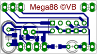
For my class of students I designed the 'definite' straddling header, that also included some stuff that almost every AVR circuit needed and that was more or less 'fool-proof'.
- By adding decoupling capacitors (100nF and 4u7F), I made sure that some microcontroller crashes that sometimes occur by switching larger currents (that cause voltage drops) wouldn't bother them too much.
- For some circuits, timing is essential and you need a crystal. However, crystals on breadboards are bothersome because of the necessary capacitors with weird, never used values that you know you have somewhere but you can never find. The thin wires on those pF capacitors make brittle contact and are the cause of unpredictable behaviour. Therefore, it is much easier to place a crystal of the highest frequency the specific AVR can handle on the board, including the SMT capacitors. If you don't use it, it doesn't affect the XT pins, so that's not to worry.
- To avoid a faulty connection of the programmer, it's better to use an IDC socket instead of a bare pin header. I used a 10-pin IDC programming header socket in this case, because the cheapest programmers seem to have 10-pin cables (and not 6). But 6 pin IDC is of course also possible. I didn't connect all ground pins though, since that couldn't be routed without an air wire. The ground pins are all connected on the programmer side, so it's not a big deal.
- For the 'breadboard' pins I now use extra long pin headers. These can be fed 'through' the board for included stability. The plastic on the top side, combined with the solder on the bottom side creates a very sturdy design. I also added a second pin beside the reset pin (just for strength) and two dummy (unconnected) pins on the other side of the board (for extra stability). Since the board now rests on four pillars of pins, it's easier to connect and disconnect the programming header; the board stays firmly fixed in place on your breadboard.
- The extra pin next to the reset pin is on pin D0, so I could as well make use of it and add a Led there to make it easy to flash your first blinkled program to test your AVR programming chain (and/or the specific AVR). The only downside there is, that if you are going to use the serial on higher speeds, the Led could be bothersome. A next version might have a jumper there to disconnect the led if necessary.
When making the boards, it's important to take the surplus board next to the pins into account. If there is too much board, it will be hard to use all of the remaining 3 holes of the breadboard row. And sometimes you really need that 3rd one! Make the boards as compact as possible.
Another small error in the design layout is that the IDC sockets are much wider than one would expect, so the 10uF capacitor had to be tilted to mount it, because the PCBs had already been made. I've made a new design that fixes these errors (the tilted capacitor, the jumper and the remaining ground pins of the IDC).
Download
The latest design, in Eagle format can be downloaded here, or by clicking on the PCB layout diagram.