Reading Rotary Encoders
From Just in Time
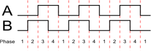
Many rotary encoders work in quadrature mode. This means that their signals will look somewhat like what is shown on the right
. Note that the ones you turn by hand normally have one noticable 'click' for every full cycle (phases 1-4 in the image). Whether the pins are low-active, or high-active and which pin is which is normally not important, though it does influence which direction is considered 'up' and which is 'down'.
AVR code
The following code runs in a timer interrupt. Most timer frequencies will do, as long as it's fast enough to see all states in the interrupt. Of course, you can also use a pin change interrupt if you want to be sure. The code assumes a read function that reads the state of the two encoder output pins and puts them in the bottom two bits of the return value. Any two adjacent bits will do if the constant 0x02 is adapted. Do take care that timer.state in this example counts up or down for every state change, which means that the counter is increased four times for every click.
/// Timer interrupt
ISR( TIMER1_COMPA_vect)
{
	// previously seen value of encoder bits.
	static uint8_t previous = 0;

	// get the encoder state
	uint8_t current = read(encoder); // this reads the A and B line values in the lower 2 bits.
	if (current != previous)
	{
		// there's a change, decide whether we count up or down.
		if ((previous ^ (current << 1)) & 0x02)
		{
			--timer_state.value;
		}
		else
		{
			++timer_state.value;
		}
		timer_state.value_changed = 1;

		//timer_state.value = current;
		previous = current;
	}

}
The code works by comparing line A at time t with line B at time t-1. Looking at the drawing above, you can see that when we move to the right in this diagram, the state of line A seems to follow that of line B, which means that A(t) == B(t-1) if the encoder moves to the right. Conversely, if the encoder moves to the left A(t) will always be the opposite of B(t-1). An exclusive OR of A(t) and B(t-1) is used to compare the two values.
SX code
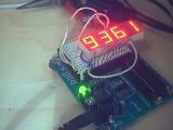
The following SX28 assembly contains two virtual pheripherals:
- Reading a rotary encoder
- driving 4 7-segment led displays
Reading the encoder starts at label ReadEncoder.
The main program just loops and does nothing. The first vp communicates directly with the second. This code is an adapted version (made into a vp) of sources found on sxlist.
;=======================================================================

 ;TITLE:         4x7segments.src
 ;
 ;PURPOSE:       Read pulses from a rotary encoder, adapt a counter
 ;			and output to 4 7-segment led displays
 ;
 ;AUTHOR:        Danny Havenith
 ;
 ;REVISIONS:
 ;  <mm/dd/yy> - <details of revision>
 ;               <more details of same revision>
 ;
 ;CONNECTIONS:
 ;	ra.0 and ra.1: encoder inputs
 ;	rc: led segment outputs
 ;	rb.0-4: led column outputs
 ;
 ;=======================================================================


 ;-------------------------- DEVICE DIRECTIVES --------------------------

 		DEVICE		SX28,OSC4MHZ,TURBO
 		DEVICE		STACKX, OPTIONX
 		IRC_CAL		IRC_SLOW

 		RESET		Initialize

 ;------------------------------ CONSTANTS ------------------------------

 TicksPerMs	EQU	20	; interrupts per ms
 CyclesPerTick	EQU	200	; cycles per interrupt


 ------------------------------ VARIABLES ------------------------------
 			ORG	$10

 BankLeds	= $

 MSTimer		DS	1
 CurrentDigit	DS	1
 CurrentColumn	DS	1
 Digits		DS	4

 CounterA	DS	1
 CounterB	DS	1
 CounterC	DS	1

 BankEncoder	= $
 EncoderState	DS 	1
 temp		DS	1


 ColumnPort	EQU 	rb
 RowPort		EQU	rc

 EncoderPort	EQU	ra 	; port for the rotary encoder
 EncoderMask	EQU	$03	; which bits to use.

 ;---------------------------- DEBUG SETTINGS ---------------------------

 		FREQ	4_000_000

 ;		WATCH	<Symbol>,<bit count>,<format>

 WKED_W		equ	$0A		;Write MIWU/RB Interrupt edge setup, 0 = falling, 1 = rising
 WKEN_W		equ	$0B		;Write MIWU/RB Interrupt edge setup, 0 = enabled, 1 = disabled
 ST_W		equ	$0C		;Write Port Schmitt Trigger setup, 0 = enabled, 1 = disabled
 LVL_W		equ	$0D		;Write Port Schmitt Trigger setup, 0 = enabled, 1 = disabled
 PLP_W		equ	$0E		;Write Port Schmitt Trigger setup, 0 = enabled, 1 = disabled
 DDIR_W		equ	$0F		;Write Port Direction

 RA_latch	equ	%00000000		;SX18/20/28/48/52 port A latch init
 RA_DDIR		equ	%11111111		;see under pin definitions for port A DDIR value
 RA_LVL		equ	%00000000		;SX18/20/28/48/52 port A LVL value
 RA_PLP		equ	%11111111		;SX18/20/28/48/52 port A PLP value

 RB_latch	equ	%00000000		;SX18/20/28/48/52 port B latch init
 RB_DDIR		equ	%11110000		;SX18/20/28/48/52 port B DDIR value
 RB_ST		equ	%11111111		;SX18/20/28/48/52 port B ST value
 RB_LVL		equ	%00000000		;SX18/20/28/48/52 port B LVL value
 RB_PLP		equ	%11111111		;SX18/20/28/48/52 port B PLP value

 RC_latch	equ	%00000000		;SX18/20/28/48/52 port C latch init
 RC_DDIR		equ	%00000000		;SX18/20/28/48/52 port C DDIR value
 RC_ST		equ	%11111111		;SX18/20/28/48/52 port C ST value
 RC_LVL		equ	%00000000		;SX18/20/28/48/52 port C LVL value
 RC_PLP		equ	%11111111		;SX18/20/28/48/52 port C PLP value

 ;-------------------------- INTERRUPT ROUTINE --------------------------
 		ORG	$0

 ;	break Interrupt
 Interrupt
 ; timer
 	bank BankLeds
 	mov w, #TicksPerMs
 	dec MSTimer
 	snz
 	mov MSTimer, w
 	sz
 	jmp EndInterrupt

 	mov w, #Digits
 	add w, CurrentDigit
 	mov fsr, w
 	mov w, IND
 	call Decode
 	clr ColumnPort
 	mov RowPort, w
 	mov ColumnPort, CurrentColumn

 	; next column
 	clc
 	rr CurrentColumn	; rotate column left
 	mov w, #%00001000
 	inc CurrentDigit		; increase digit counter
 	snc 		; reset if digit = 4
 	mov CurrentColumn, w
 	snc
 	clr CurrentDigit

 :EndLeds

 	break ReadEncoder
 ReadEncoder
         mov w, EncoderPort           ;get change between current and previous
                             ;encoder state in w
         xor w, EncoderState    ;

         xor EncoderState, w    ;update state and preserve difference in w

         and w, #EncoderMask         ;check if there is change
         snz
          jmp :EndEncoder       ;no change, read encoder again

         ;if both bits changed, this will be an error, but we ignore it here
         ;xor w, #$03
         ;skpnz
         ; jmp enc_error

         ;calculate direction in temp.1
         mov temp, w
         mov w, <<EncoderState
         xor w, EncoderState
         xor temp, w

         sb temp.1
          call EncoderIncrease       ;Encoder moved up
         snb temp.1
          call EncoderDecrease       ;Encoder moved down

 :EndEncoder

 EndInterrupt
 	mov w, #-CyclesPerTick
 	retiw

 EncoderIncrease
 	inc	Digits + 3
 	cjne	Digits + 3, #10, :EndInc
 	clr 	Digits + 3

 	inc	Digits + 2
 	cjne	Digits + 2, #10, :EndInc
 	clr 	Digits + 2

 	inc	Digits + 1
 	cjne	Digits + 1, #10, :EndInc
 	clr 	Digits + 1

 	inc	Digits
 	cjne	Digits, #10, :EndInc
 	clr 	Digits
 :EndInc
 	retp

 EncoderDecrease
 	dec	Digits + 3
 	cjne	Digits + 3, #$FF, :EndDec
 	mov	Digits + 3, #09

 	dec	Digits + 2
 	cjne	Digits + 2, #$FF, :EndDec
 	mov	Digits + 2, #09

 	dec	Digits + 1
 	cjne	Digits + 1, #$FF, :EndDec
 	mov	Digits + 1, #09

 	dec	Digits
 	cjne	Digits, #$FF, :EndDec
 	mov	Digits, #09
 :EndDec
 	retp

 Decode
 	and w, #$0F
 	jmp PC+w
 	retw %00000101 ;0
 	retw %11011101 ;1
 	retw %10000110 ;2
 	retw %10010100 ;3
 	retw %01011100 ;4
 	retw %00110100 ;5
 	retw %00100100 ;6
 	retw %10011101 ;7
 	retw %00000100 ;8
 	retw %00010100 ;9
 	retw %00001100 ;A
 	retw %01100100 ;b
 	retw %00100111 ;C
 	retw %11000100 ;d
 	retw %00100110 ;E
 	retw %00101110 ;F

 ;------------------------ INITIALIZATION ROUTINE -----------------------

 Initialize
 		; Configure all ports
 		mov 	m, #ST_W			;point MODE to write ST register
 		mov     w,#RB_ST            	;Setup RB Schmitt Trigger, 0 = enabled, 1 = disabled
 		mov	!rb,w
 		mov     w,#RC_ST            	;Setup RC Schmitt Trigger, 0 = enabled, 1 = disabled
 		mov	!rc,w
 		mov 	m, LVL_W			;point MODE to write LVL register
 		mov     w,#RA_LVL            	;Setup RA CMOS or TTL levels, 0 = TTL, 1 = CMOS
 		mov	!ra,w
 		mov     w,#RB_LVL            	;Setup RB CMOS or TTL levels, 0 = TTL, 1 = CMOS
 		mov	!rb,w
 		mov     w,#RC_LVL            	;Setup RC CMOS or TTL levels, 0 = TTL, 1 = CMOS
 		mov	!rc,w

 		mov 	w,#RA_PLP            	;Setup RA Weak Pull-up, 0 = enabled, 1 = disabled
 		mov	!ra,w
 		mov     w,#RB_PLP            	;Setup RB Weak Pull-up, 0 = enabled, 1 = disabled
 		mov	!rb,w
 		mov     w,#RC_PLP            	;Setup RC Weak Pull-up, 0 = enabled, 1 = disabled
 		mov	!rc,w

 		mov 	m, #DDIR_W			;point MODE to write DDIR register
 		mov	w,#RA_DDIR		;Setup RA Direction register, 0 = output, 1 = input
 		mov	!ra,w
 		mov	w,#RB_DDIR		;Setup RB Direction register, 0 = output, 1 = input
 		mov	!rb,w
 		mov	w,#RC_DDIR		;Setup RC Direction register, 0 = output, 1 = input
 		mov	!rc,w

 		mov     w,#RA_latch          	;Initialize RA data latch
 		mov     ra,w
 		mov     w,#RB_latch         	;Initialize RB data latch
 		mov     rb,w
 		mov     w,#RC_latch          	;Initialize RC data latch
 		mov     rc,w

 ; zero all ram (SX28)
 		clr	fsr			;reset all ram banks
 :zero_ram	sb	fsr.4			;are we on low half of bank?
 		setb	fsr.3			;If so, don't touch regs 0-7
 		clr	ind			;clear using indirect addressing
 		incsz	fsr			;repeat until done
 		jmp	:zero_ram

 :init_leds	bank BankLeds
 		mov CurrentDigit, #0
 		mov CurrentColumn, #1

 ;---------------------------- MAIN PROGRAM -----------------------------

 Main

 	mov Digits, #1
 	mov Digits + 1, #2
 	mov Digits + 2, #3
 	mov Digits + 3, #4
 	mov	!option, #%10011111	;enable rtcc interrupt

 :loop
  	jmp :loop


 ;----------------------------- SUBROUTINES -----------------------------

 ;<GlobalLabel>
 ;<detailed description of routine>

 ;		<inst>	<op1>,<op2>		;<time>	<comment>
