RGB Light Show (Wired/Wireless)
From Just in Time
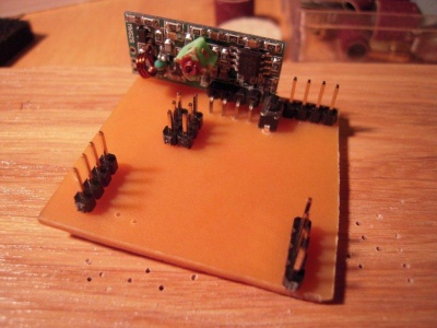
We were able to get our hands on a set of par-56 RGB led spots. We thought it would be fun to create a wireless controller for these. While experimenting, we soon found out that you may not want your stage lighting depend on the reliability of a cheap 433Mhz transmitter/receiver pair, so we soon added an option to send the command through a wire as well.
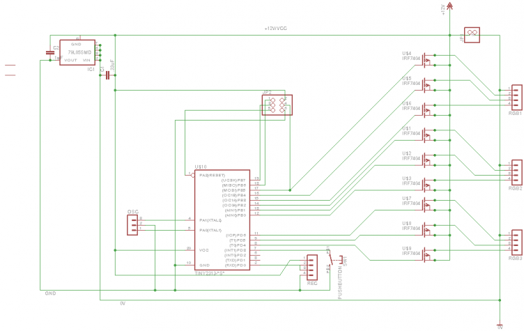
Each controller is based on an ATTiny 2313 and performs PWM control on 3 separate RGB spots (9 channels). Since the whole PWM is controlled through timer interrupts in software, 8 bits is the best resolution we could manage. This is pretty basic for an RGB spot, especially given that our perception of brightness is not linear to the relative pulse widths (or in other words: going from 1/256 to 2/256 pulse has a much bigger effect than moving from 200/256 to 201/256). Note that the schematics are for common-cathode leds, hence the P-channel mosfets.
The software implements 3 faders that control 3 channels each. Every fader uses Bresenham's line algorithm to smoothly change the 3 RGB values from some starting color to an end color, essentially creating a 4D line (R,G,B,time). Interrupt-driven pwm control makes sure that the RGB-values are translated into pulse widths.
Protocol
The protocol consists of three stacked protocol layers, from low to high
- RS-232, 1 start bit, 1 stop bit, 8 data bits. We expect ttl-level at the pins. In essence, the UART input pin of the AVR is connected directly to the data line of the 433 Mhz receiver.
- Our own packet protocol, with 8 bit addressing and CRC. See the table below.
- The spotlight command protocol.
packet protocol
packets look like this:
| preamble (any sequence of zeros) | end-of-preamble (0x55) | address (1-255, 0 means broadcast) | size-of-data minus one (0-15), upper 4 bits unused | data bytes | 2 byte CRC |
The CRC is a 32 bit xmodem checksum. It covers only the data bytes. In hindsight, it should have covered the address and size byte as well and we may change the protocol some day to do just that
Command bytes
The commands for the spotlight controller are transported as sequences of data bytes inside the packets as described above. Each sequence consists of at least a command byte. Depending on the command, the command byte may be followed by parameters. In general, the most significant 4 bits of the command word describe the command (room for 16 commands), the lower 2 bits may contain a spot number, depending on the command. Arguments in <angle brackets> in the following table are encoded in the lower 2 bits of the command byte.
| value | meaning | arguments | comments |
|---|---|---|---|
| 0x90 | wait_for_fader | <spot> | Halt processing further commands until the given fader has finished |
| 0xA0 | fade | <spot> time red green blue | Let the spot fade from its current color to the given one. The time is given in units of 1/50 s and must be in the range 0 - 255. |
| 0xB0 | set_initial | <spot> red green blue | Set the initial (switch-on) values for a spot |
| 0xC0 | hold | none | Pause all faders |
| 0xD0 | resume | none | Resume all faders |
| 0xE0 | set | <spot> red green blue | Immediately set the color for the given spot. |
| 0xF0 | address | new addres | Set the device address if the address button of the controller is pressed simultaneously. This command is typically broadcast to all controllers while the user presses the button on one of them. |
Commands are treated as a stream of bytes. That is, a command could be spread over multiple packets and a single packet could contain multiple commands. An example sequence would be:
   0xE1,0x0,0x0,0x0,
   0xE0,0xFF,0x0,0xFF,
   0xA1,0x32,xFF,0xFF,0xFF,
   0x91,
   0xA0,0x32,0x0,0x0,0x0
This sequence consists of 5 commands:
- Switch off spot 1 (rgb: 0,0,0)
- Set spot 0 to purple (rgb: 255, 0, 255)
- Fade spot 1 in 50 ticks (1s) to white
- Wait for spot 1 to finish fading
- Fade spot 0 in 1s to black
Software
The sources are available at github.
The software implements 6 8-bit pwm channels, R, G and B each for two spots. On top of that is an implementation of Bresenham's algorithm to create automated smooth color transitions. All of this is handled in the AVRs timer interrupt. The UART receive interrupt (USART_RX_vect) handles the packet decoding and puts the payload bytes in a circular buffer.
The main program just picks up the payload bytes, interprets them as commands and programs the faders and LED states accordingly.
Schematic & Board
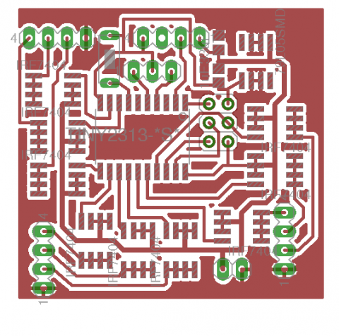
As stated before, the leds are common-cathode. To keep the control as simple as possible the power is somewhat unorthodox: given a 12V power source, we create one extra 7V source. The 7V acts as GND for the controller, while the 12V line acts as Vcc. This way, the AVR can alternate the gates of the P-channel mosfets between 7V and 12V.


