Cheapest ever 433 Mhz transceiver for PCs
From Just in Time
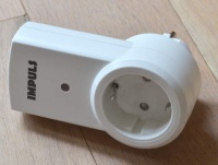
Several shops offer cheap 433Mhz RF remote controlled switches. These are nice, but they introduce a few problems as well:
- The cheap ones all have different remote controls, using different protocols, leading to our own basket of remotes problem;
- We often want to control our light switches from our PC, not from the remote controls.
What if you could use a PC to transmit all the RF signals to switch on- and off all devices, and have that PC learn the signals from the remotes? As it turns out, this is very easy to do. Most of these remote control devices use a digital serial protocol of about 1kbaud superimposed on the 433 Mhz signal. That 1kbaud falls well within the range of what a PC sound card can generate or sample. Furthermore, receivers that extract the digital signal and transmitters that turn the digitial signals into an RF signal are readily available.
This page describes how to create an absurdly low-cost USB 433 Mhz transceiver that can serve as a good starting point for your home automation projects.
We're also working on an AVR ("arduino") based version that transmits cleaner signals.
Hardware
Before you read any further: the hardware described below is really a very dirty hack and users have reported problems with noise on the input of this device. A more thought-through piece of hardware that does essentially the same thing is described on Avians blog (thanks for your comment Avian). You could first try the hack described below, and if that doesn't work consider Avians approach...
To build this, all you need is a 433Mhz transmitter/receiver pair (or 315 Mhz if appropriate in your country) and a usb audio-"card" (links are to ebay search results). All in all, with the ever decreasing prices for these devices this is about $2,- in materials. Now give yourself a dollar for the soldering work that is about to happen.
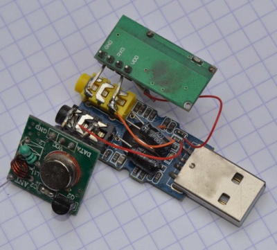
Next: some soldering. The result will surely not win any beauty contests and may constitute criminally inhumane treatment of innocent electronics (AKA 'CITIE', AKA 'hack'):
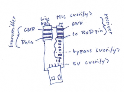
Obviously, we need to connect the transmitter to the audio output and the receiver to the mic input. The wiring is as follows for the transmitter (see this page for terminology). Bold words refer to pins on the transmitter:
- GND is connected to the sleeve contact on the socket.
- data is connected to the tip contact (left audio channel)
- Vcc to USB 5V, the red wire in the picture.
For the receiver:
- GND to sleeve
- Vcc to USB 5V, red wire
- RxD to tip (for mechanical stability only) and to a bypass (orange wire).
The RxD connection takes some explanation. These USB sound cards have a mic input connector which normally routes the signal throug a high pass filter. Since we want the 'raw' data from the receiver without filtering, we need to bypass that filter. Again, this is not too difficult: we need to find the filtering capacitor. The capacitor in question is found with a volt meter by looking for one that is directly connected to the input (the tip contact). This is the capacitor we need to bypass, and in this particular case I've done it by soldering a wire from the tip connector to the other side of the capacitor.
Note that the exact capacitor to bypass will vary from one soundcard to another. I have found two variations in two different batches bought on ebay. you should definitely look for the right capacitor using the multimeter method.
Also note that you can still get a decent signal without bypass, i.e. by connecting the receiver input to the mic input line. You'll notice that the high-pass filter will push the signal "downwards" to become symmetrical around zero.
Software
Learning remote control signals
After connecting our Frankensteinian contraption, our PC will have another audio 'card'. Mine identifies itself als "Generic USB Audio Device". This device can now be used to record remote signals as if they were audio and to play them back as audio files as well.
I use Audacity to record keystrokes on the remote. It's as easy as pressing the Record-button in Audacity, pressing the key that we want to record on the remote and then pressing the stop button. You should see that Audacity has recorded a few repetitions of the same sequence—the image above zooms in on two such repetitions. You can now verify that the signal was correctly recorded by playing it back to our contraption. The switch should behave as if you pressed the key on the remote. Playing back only one occurrence of such a sequence usually doesn't work, so I try to find the minimum amount of repetitions that reproduce the switching behaviour. Then I save those repetitions in a single wav-file. Now repeat the procedure for the other keys of a remote and create a wav-file for each key. You should end up with wav-files with names like onA.wav, offA.wav, onB.wav, etc.
Quick-'n-easy
If you don't like to spend time on configuring existing home automation software and just want to switch something from a command line or script, you only need a command line audio player that is capable to play your sounds to a given audio card. On Windows, vlc might work (I haven't tried). On linux with ALSA installed, aplay fits the bill exactly. In your script, call aplay with the name of the keystroke-file and specify the soundcard, e.g.:
aplay -D plughw:2,0 onA.wav;
Fun project: The script below—when run in the background—will switch off a light when my Ubuntu (gnome) screen saver locks the screen and it will switch it on when I log in again. The light is a halogen spot that lights up the wall behind my monitor... <source lang='bash'> dbus-monitor --session "type='signal',interface='org.gnome.ScreenSaver'" | ( while true; do read X; if echo $X | grep "boolean true" &> /dev/null; then aplay -D plughw:2,0 offC.wav; elif echo $X | grep "boolean false" &> /dev/null; then aplay -D plughw:2,0 onC.wav; fi done ) </source>
Integration with home automation software
Instead of writing all the home automation software ourselves, we'd rather create a plugin to integrate this hardware with existing home automation. There seems to be no real widespread, open (and programming language agnostic) protocol for home automation devices (this appears to be a general issue with the internet of things). There is an open protocol though, which is xPL and there is a home automation suite that supports it, domogik. Therefore it seemed like a good idea to implement an xPL bridge for our contraption, and that is exactly what we've done. The source code for our xPL bridge is available on GitHub. This bridge is a small program that runs on linux only (think Raspberry Pi/Beaglebone) and that listens to X10 commands from an xPL hub. This is fairly easy to set up with domogik and it works, as can be seen in the short video below.
Comments? Questions?
{{#set: |Article has average rating={{#averagerating:}} }} {{#showcommentform:}}
{{#ask: Belongs to article::Cheapest ever 433 Mhz transceiver for PCsModification date::+
 | ?Has comment person
 | ?Has comment date
 | ?Has comment text
 | ?Has comment rating
 | ?Belongs to comment
 | ?Comment was deleted#true,false
 | ?Has comment editor
 | ?Modification date
 | ?Has attached article
 | format=template
 | template=CommentResult
 | sort=Has comment date
 | order=asc
 | link=none
 | limit=100
}}


