Difference between revisions of "Roland FD-8 Issues: Hall Sensor Modification"
From Just in Time
m |
|||
| (49 intermediate revisions by 2 users not shown) | |||
| Line 1: | Line 1: | ||
| − | + | This page describes one of two solutions to common issues with the Roland FD-8 hi-hat pedal. Both solutions replace the film resistor with a Hall effect sensor. This solution uses discrete components and you may find it easier to construct. A low-cost microcontroller-based version is described [[Digital FD-8 pedal|on this page]]. | |
| − | + | Both editors of the Justintime pages have a Roland TD-3 electronic drum kit. This kit plays quite nicely, but after some years the responsiveness of the Hi-hat pedal seems to worsen. We are not the only ones who have noticed this; google for 'roland fd-8 issues' to find widespread complaints and hacks/solutions people have come up with. Most solutions have to do with adjusting the mechanical pressure on the variable film resistor in the pedal. | |
| − | Although the film resistor is very variable, the TD-3 | + | However, I wanted to completely get rid of the film resistor and replace it with an electronic alternative that has no contact issues AND had the possibility to adjust the half-open range to personal taste. The obvious choice for the detection was a (linear) Hall Sensor, but this would have to be translated to a variable resistor for the TD-3. The first design thoughts were MCU based with an ADC and programmable variable resistor, but after some more (clever) thinking it became clear that a circuit with two comparators and two analog switches would work just as well and might be a lot simpler. Another important consideration is that it might be easier for the average FD-8 owner (other than the two of us) to recreate. |
| + | |||
| + | Although the film resistor is very variable, the TD-3 hi-hat recognizes three positions from the resistor: | ||
* closed (short, 0R to 5K) | * closed (short, 0R to 5K) | ||
* half (5K to 15K) | * half (5K to 15K) | ||
* closed (15K and up) | * closed (15K and up) | ||
| − | Finding a linear Hall Sensor can be hard. Pay attention: most Hall Sensors are on/off type and have hysteresis circuit inside. These can not be used, because we have to detect at least two switching points. | + | ==Electronics== |
| + | Finding a linear Hall Sensor can be hard. Pay attention: most Hall Sensors are on/off type and have hysteresis circuit inside. These can not be used, because we have to detect at least two switching points. I used a Honeywell SS490, but I suspect any Linear (Ratiometric) Hall Sensor should do. Also be aware that the sensor is polarity-sensitive; the circuit is designed for voltage increase when the magnet draws near (4.5 - 8.5V), but if you flip the magnet the voltage will decrease!! | ||
| + | |||
| + | For powering the circuit we branch off the TD-3 power supply. Be careful: the Roland power supply states 9V output, but it outputs about 11.5V. Since my Hall Sensor max was 10.5V, a regulator was necessary. 9V seemed a good pick. Using a small Neodymium magnet the sensor had a working range of 4.5V to 8.5V. I used a plastic Lego brick because it was available and about the right size, and most of all because it was sturdy plastic. After starting of with a metal construction, this was abandoned because I was worried the metal would interfere with the magnetic field and influence the sensor readings, so plastic seemed a better pick. | ||
| + | |||
| + | By making the comparator inputs adjustable with potmeters, the sensitivity range of the FD-8 half and closed settings can be made very flexible. The circuit is not very complex, so it could very well be made on veroboard or stripboard. I have made a SMT PCB myself, because I prefer working in SMT. Check out the [[Hall-High-Hat-Hack-Schematic|schematic]], [[PCB Layout]] and [[Media:HallHighHat Eagle Files.7z |Eagle Files]]. | ||
| + | |||
| + | The prototype circuit works very well and makes the Hi-Hat a lot easier to play e.g. provides a much more reliable closing action. The only 'downside' of the circuit is that the foot-sound is always on full volume. I suspect that this can be adjusted by increasing the 0R value, but this has yet to be tested. | ||
| + | |||
| + | ==Construction== | ||
| + | Below are some pics. These pictures were made before the DC connectors had arrived. These 2.1mm DC Power plugs are intended to make use of the original TD3 power supply; the pedal will feature 2 parallel plugs, one for power supply input and the TD-3 module can be connected to the other power plug via a cable. | ||
| + | |||
| + | Below are some pics of the not-yet-finished build. Mechanically, this is exactly the same as in the [[Digital FD-8 pedal|microcontroller-based concept]]. | ||
| + | |||
| + | [[File:Hall Sensor and Strip.JPG]] | ||
| + | |||
| + | The Magnet sticks to the metal by magnetism, but is also glued with superglue to avoid shift. The Hall Sensor and Lego brick are set using doublesided tape and [[secured by a tie-wrap]]. Also visible is the original variable film-resistor. This is left intact, so it is always possible to return to using the original mechanical film-resistor mechanism. The output of the hall-sensor-resistor-circuit is routed to a new jack output on the other side of the pedal, as can be seen on this picture, since the original output is on the left side. | ||
| + | |||
| + | [[File:External Pots.JPG]] | ||
| + | |||
| + | The external pots are for adjusting the sensitivity of the closed and half-open state. If you do not intend to tweak trimpots would do fine too. | ||
| + | |||
| + | [[File:Internal Wiring.JPG]] | ||
| + | |||
| + | The Hall Sensor is connected by a pin header connector, so it is easier to take the pedal apart. Fortunately there is enough spare room in the pedal for the circuitry. | ||
| − | + | [[File:FD8 with Knobs.JPG]] | |
| − | + | Disclaimer: Use this info at your own risk. We take no responsibility for any damaged equipment! | |
| − | + | ==Comments? Questions?== | |
| + | {{ShowComments|show=True}} | ||
Latest revision as of 18:35, 22 August 2015
This page describes one of two solutions to common issues with the Roland FD-8 hi-hat pedal. Both solutions replace the film resistor with a Hall effect sensor. This solution uses discrete components and you may find it easier to construct. A low-cost microcontroller-based version is described on this page.
Both editors of the Justintime pages have a Roland TD-3 electronic drum kit. This kit plays quite nicely, but after some years the responsiveness of the Hi-hat pedal seems to worsen. We are not the only ones who have noticed this; google for 'roland fd-8 issues' to find widespread complaints and hacks/solutions people have come up with. Most solutions have to do with adjusting the mechanical pressure on the variable film resistor in the pedal.
However, I wanted to completely get rid of the film resistor and replace it with an electronic alternative that has no contact issues AND had the possibility to adjust the half-open range to personal taste. The obvious choice for the detection was a (linear) Hall Sensor, but this would have to be translated to a variable resistor for the TD-3. The first design thoughts were MCU based with an ADC and programmable variable resistor, but after some more (clever) thinking it became clear that a circuit with two comparators and two analog switches would work just as well and might be a lot simpler. Another important consideration is that it might be easier for the average FD-8 owner (other than the two of us) to recreate.
Although the film resistor is very variable, the TD-3 hi-hat recognizes three positions from the resistor:
- closed (short, 0R to 5K)
- half (5K to 15K)
- closed (15K and up)
Electronics
Finding a linear Hall Sensor can be hard. Pay attention: most Hall Sensors are on/off type and have hysteresis circuit inside. These can not be used, because we have to detect at least two switching points. I used a Honeywell SS490, but I suspect any Linear (Ratiometric) Hall Sensor should do. Also be aware that the sensor is polarity-sensitive; the circuit is designed for voltage increase when the magnet draws near (4.5 - 8.5V), but if you flip the magnet the voltage will decrease!!
For powering the circuit we branch off the TD-3 power supply. Be careful: the Roland power supply states 9V output, but it outputs about 11.5V. Since my Hall Sensor max was 10.5V, a regulator was necessary. 9V seemed a good pick. Using a small Neodymium magnet the sensor had a working range of 4.5V to 8.5V. I used a plastic Lego brick because it was available and about the right size, and most of all because it was sturdy plastic. After starting of with a metal construction, this was abandoned because I was worried the metal would interfere with the magnetic field and influence the sensor readings, so plastic seemed a better pick.
By making the comparator inputs adjustable with potmeters, the sensitivity range of the FD-8 half and closed settings can be made very flexible. The circuit is not very complex, so it could very well be made on veroboard or stripboard. I have made a SMT PCB myself, because I prefer working in SMT. Check out the schematic, PCB Layout and Eagle Files.
The prototype circuit works very well and makes the Hi-Hat a lot easier to play e.g. provides a much more reliable closing action. The only 'downside' of the circuit is that the foot-sound is always on full volume. I suspect that this can be adjusted by increasing the 0R value, but this has yet to be tested.
Construction
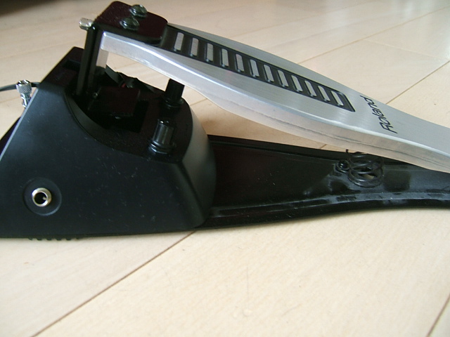
Below are some pics. These pictures were made before the DC connectors had arrived. These 2.1mm DC Power plugs are intended to make use of the original TD3 power supply; the pedal will feature 2 parallel plugs, one for power supply input and the TD-3 module can be connected to the other power plug via a cable.
Below are some pics of the not-yet-finished build. Mechanically, this is exactly the same as in the microcontroller-based concept.
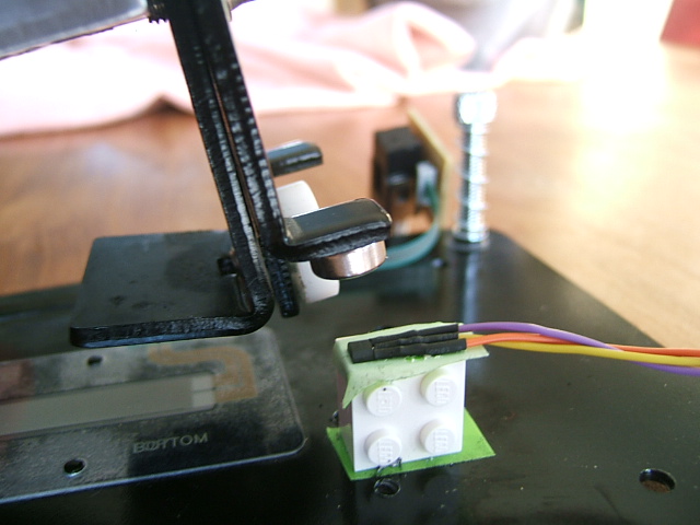
The Magnet sticks to the metal by magnetism, but is also glued with superglue to avoid shift. The Hall Sensor and Lego brick are set using doublesided tape and secured by a tie-wrap. Also visible is the original variable film-resistor. This is left intact, so it is always possible to return to using the original mechanical film-resistor mechanism. The output of the hall-sensor-resistor-circuit is routed to a new jack output on the other side of the pedal, as can be seen on this picture, since the original output is on the left side.
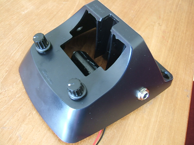
The external pots are for adjusting the sensitivity of the closed and half-open state. If you do not intend to tweak trimpots would do fine too.
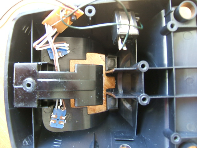
The Hall Sensor is connected by a pin header connector, so it is easier to take the pedal apart. Fortunately there is enough spare room in the pedal for the circuitry.
Disclaimer: Use this info at your own risk. We take no responsibility for any damaged equipment!
Comments? Questions?
{{#set: |Article has average rating={{#averagerating:}} }} {{#showcommentform:}}
{{#ask: Belongs to article::Roland FD-8 Issues: Hall Sensor ModificationModification date::+
 | ?Has comment person
 | ?Has comment date
 | ?Has comment text
 | ?Has comment rating
 | ?Belongs to comment
 | ?Comment was deleted#true,false
 | ?Has comment editor
 | ?Modification date
 | ?Has attached article
 | format=template
 | template=CommentResult
 | sort=Has comment date
 | order=asc
 | link=none
 | limit=100
}}


