Difference between revisions of "RGB Light Show (Wired/Wireless)"
From Just in Time
m |
|||
| Line 5: | Line 5: | ||
The software implements 3 faders that control 3 channels each. Every fader uses Bresenham's line algorithm to smoothly change the 3 RGB values from some starting color to an end color, essentially creating a 4D line (R,G,B,time). Interrupt-driven pwm control makes sure that the RGB-values are translated into pulse widths. | The software implements 3 faders that control 3 channels each. Every fader uses Bresenham's line algorithm to smoothly change the 3 RGB values from some starting color to an end color, essentially creating a 4D line (R,G,B,time). Interrupt-driven pwm control makes sure that the RGB-values are translated into pulse widths. | ||
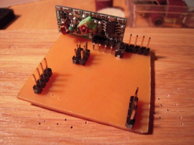
| + | [[File:spot_controller_top.jpg|400px|thumb|top side of the print with 1x4 headers for the rgb-spots, a 2x3 programming header, a push button to program a device address and a 433Mhz receiver]] | ||
==Command bytes== | ==Command bytes== | ||
In general, the most significant 4 bits describe the command (room for 16 commands), the lower 2 bits may contain a spot number, depending on the command. Arguments in ''<angle brackets>'' are encoded in the lower 2 bits of the command byte. | In general, the most significant 4 bits describe the command (room for 16 commands), the lower 2 bits may contain a spot number, depending on the command. Arguments in ''<angle brackets>'' are encoded in the lower 2 bits of the command byte. | ||
Revision as of 00:01, 7 November 2012
We were able to get our hands on a set of par-56 RGB led spots. We thought it would be fun to create a wireless controller for these. While experimenting, we soon found out that you may not want your stage lighting depend on the reliability of a cheap 433Mhz transmitter/receiver pair, so we soon added an option to send the command through a wire as well.
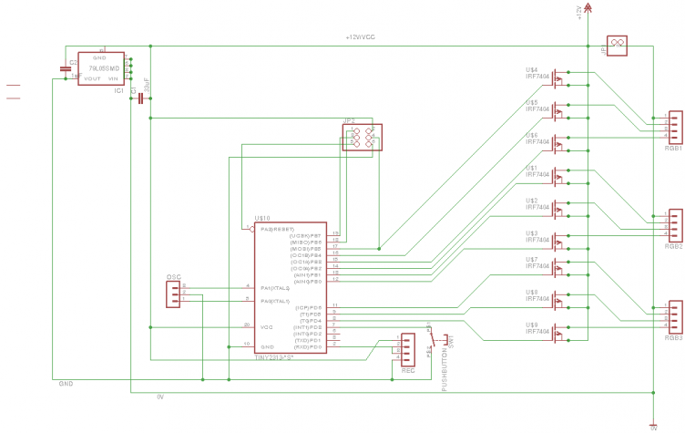
Each controller is based on an ATTiny 2313 and performs PWM control on 3 separate RGB spots (9 channels). Since the whole PWM is controlled through timer interrupts in software, 8 bits is the best resolution we could manage. This is pretty basic for an RGB spot, especially given that our perception of brightness is not linear to the relative pulse widths (or in other words: going from 1/256 to 2/256 pulse has a much bigger effect than moving from 200/256 to 201/256). Note that the schematics are for common-cathode leds, hence the P-channel mosfets.
The software implements 3 faders that control 3 channels each. Every fader uses Bresenham's line algorithm to smoothly change the 3 RGB values from some starting color to an end color, essentially creating a 4D line (R,G,B,time). Interrupt-driven pwm control makes sure that the RGB-values are translated into pulse widths.
Command bytes
In general, the most significant 4 bits describe the command (room for 16 commands), the lower 2 bits may contain a spot number, depending on the command. Arguments in <angle brackets> are encoded in the lower 2 bits of the command byte.
| value | meaning | arguments | comments |
|---|---|---|---|
| 0x90 | wait_for_fader | <fader> | halts processing further commands until the given fader has finished |
| 0xA0 | fade | <spot> time red green blue | lets the spot fade from its current color to the given one |
| 0xB0 | set_initial | <spot> red green blue | sets the initial (switch-on) values for a spot |
| 0xC0 | hold | none | stops all faders |
| 0xD0 | resume | none | resumes all faders |
| 0xE0 | set | <spot> red green blue | sets the color for the given spot |
| 0xF0 | address | new addres | sets the device address of this controller, if the address button is pressend simultaneously |


