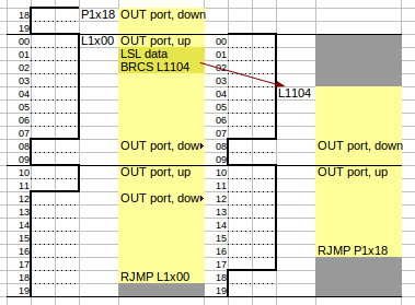
This page gives a detailed description of the WS2811@8Mhz driver code and the methodology used to create that code. The intent of the code is to send a serial signal to a given output pin in a strict 10 clockcycles/bit timing. Below follows a step-by-step explanation. You should already know a little AVR assembly language to follow the descriptions, although the code uses a very small subset of the AVR instruction set.
General description
The code contains an outer loop that loops over bytes that need to be sent. Bytes are expected in the correct order in memory, that is: in GRB order.
An inner loop sends out 2 bits at a time. Essentially there are 4 variants of the inner loop, one each for the combinations 00, 01, 10 and 11.
Normally, when creating timed loops, the extra clocktick that a jump-taken uses is compensated by adding a NOP in the not-taken code path. We cannot afford such NOP instructions here, so instead each instruction is annotated with the phase within the 20-clock cycle at which it executes and care is taken that all the output signalling is done at exactly the right phase, while other instructions are performed whenever possible.
Steps
|
|
Skeleton
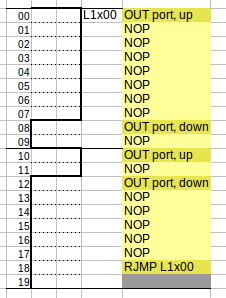
This image shows code that will continuously (and endlessly) send the bit-sequence "10" in a strict 20-clockcycle loop. This will be the skeleton that is used to add the rest of the code. Note that the OUT instructions can't be moved to any other point in time, so these form the pillars around which the rest of the code will be added.
The code is presented in 4 columns:
- a column that shows the phase within the 2-bit cycle (00-19)
- a graphical representation of the waveform shape that is being emitted
- jump labels, these are structurally named, more on that later
- the actual instructions
Labels are named Labcd, Mabcd, Habcd or Pabcd. The digits cd encode the phase at that point (the 00 in L1x00). The digits ab represent the two-bit sequence that is being sent, with x representing "don't know" (The 1x in L1x00 means that we know that the first bit is 1 and we don't know the second bit value yet). The starting letters encode where we are in the byte: L means we may be at the last 2 bits, M means we're definately not in the last two bits, and H means that we're finishing of the last bit of the complete byte sequence.
Sending a continous stream of "10101010101010..." is of limited use, so let's see if we can bring some variation in the bit sequence.
|

|
Determine second bit
Let's assume that at label L1x00 we know that the first bit is a 1 and that
|

