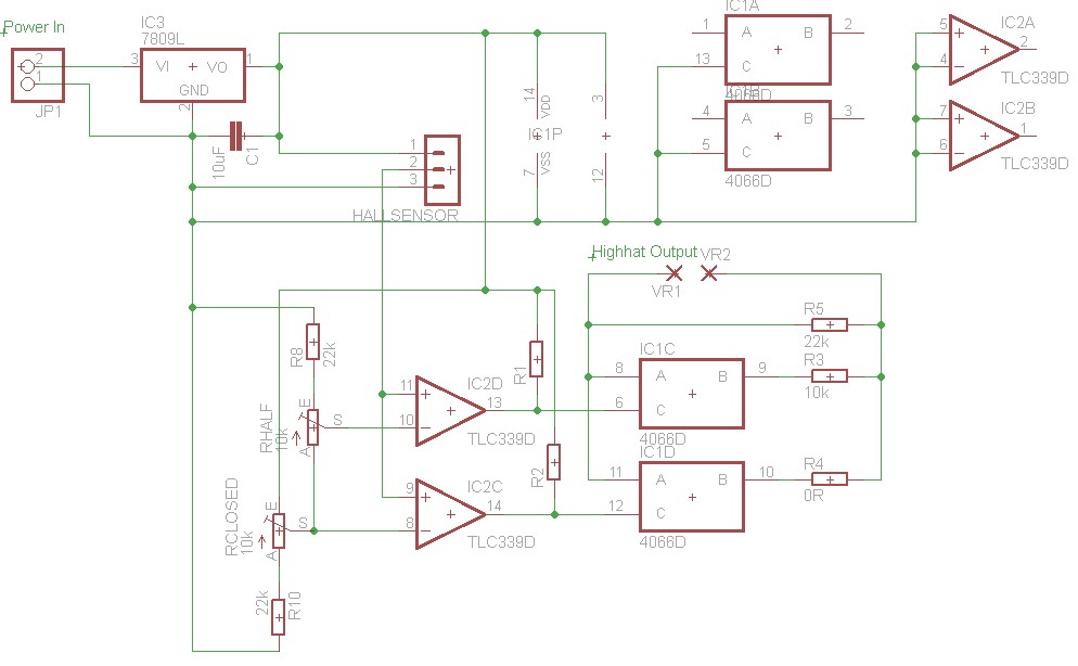
Hall-High-Hat-Hack-Schematic
From Just in Time
R1 and R2 are pull-up resistors which were necessary because the used quad comparator had open-collector outputs. If you have a comparator with output resistors, you can leave them out. VR1 and VR2 go to the output jack, polarity is irrelevant. The Hall sensor is connected by a pin header for easier assembly. The middle pin of the header is the sensor output, the others are +V and ground for the Hall Sensor.
