Difference between revisions of "Hall-High-Hat-Hack-Schematic"
From Just in Time
| Line 1: | Line 1: | ||
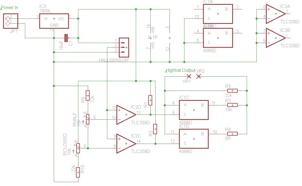
| − | R1 and R2 are pull-up resistors which were necessary because the used quad comparator had open-collector outputs. If you have a comparator with output resistors, you can leave them out. VR1 and VR2 go to the output jack, polarity is irrelevant. The Hall sensor is connected by a pin header for easier assembly. The middle pin of the header is the sensor output, pin 1 is +V and pin 3 is Ground of the sensor. R8 and R10 are intended to optimize the adjustment range of the sensitivity, but can also be left out if you use trimpots. Make sure to connect unused inputs of the leftover comparators and switches to ground or +V to avoid oscillations. | + | R1 and R2 are pull-up resistors which were necessary because the used quad comparator had open-collector outputs. If you have a comparator with output resistors, you can leave them out. VR1 and VR2 go to the output jack, polarity is irrelevant. The Hall sensor is connected by a pin header for easier assembly. The middle pin of the header is the sensor output, pin 1 is +V and pin 3 is Ground of the sensor. R8 and R10 are intended to optimize the adjustment range of the sensitivity, but can also be left out if you use trimpots. Make sure to connect unused inputs of the leftover comparators and switches to ground or +V to avoid oscillations. Make sure the Hall Sensor you have works with the 9V power supply. If you have a Hall Sensor that needs a lower supply, the whole circuit should work on +5V just as well. Just use a 7805L in that case. |
[[File:HallHighHatHack_Schematic.jpg]] | [[File:HallHighHatHack_Schematic.jpg]] | ||
Revision as of 11:30, 10 February 2011
R1 and R2 are pull-up resistors which were necessary because the used quad comparator had open-collector outputs. If you have a comparator with output resistors, you can leave them out. VR1 and VR2 go to the output jack, polarity is irrelevant. The Hall sensor is connected by a pin header for easier assembly. The middle pin of the header is the sensor output, pin 1 is +V and pin 3 is Ground of the sensor. R8 and R10 are intended to optimize the adjustment range of the sensitivity, but can also be left out if you use trimpots. Make sure to connect unused inputs of the leftover comparators and switches to ground or +V to avoid oscillations. Make sure the Hall Sensor you have works with the 9V power supply. If you have a Hall Sensor that needs a lower supply, the whole circuit should work on +5V just as well. Just use a 7805L in that case.
