Roland FD-8 Issues: Hall Sensor Modification
From Just in Time
Both editors of the Justinintime pages have a Roland TD-3 electronic drum kit. This kit plays quite nicely, but after some years the responsiveness of the High-hat pedal seems to worsen. We are not the only ones who have noticed this; google for 'roland fd-8 issues' to find widespread complaints and hacks/solutions people have come up with. Most solutions have to do with adjusting the mechanical pressure on the variable film resistor in the pedal.
However, Vincent wanted to completely get rid of the film resistor and replace it with an electronic alternative that has no contact issues. The obvious choice was a (linear) Hall Sensor. The first design thoughts were MCU based with an ADC and programmable variable resistor, but after some more (clever) thinking it became clear that a circuit with two comparators and two analog switches would work just as well and might be a lot simpler. Another important consideration is that it might be easier for the average FD-8 owner (other than the two of us) to recreate.
Although the film resistor is very variable, the TD-3 highhat recognizes three positions from the resistor:
- closed (short, 0R to 5K)
- half (5K to 15K)
- closed (15K and up)
Finding a linear Hall Sensor can be hard. Pay attention: most Hall Sensors are on/off type and have hysteresis circuit inside. These can not be used, because we have to detect at least two switching points.
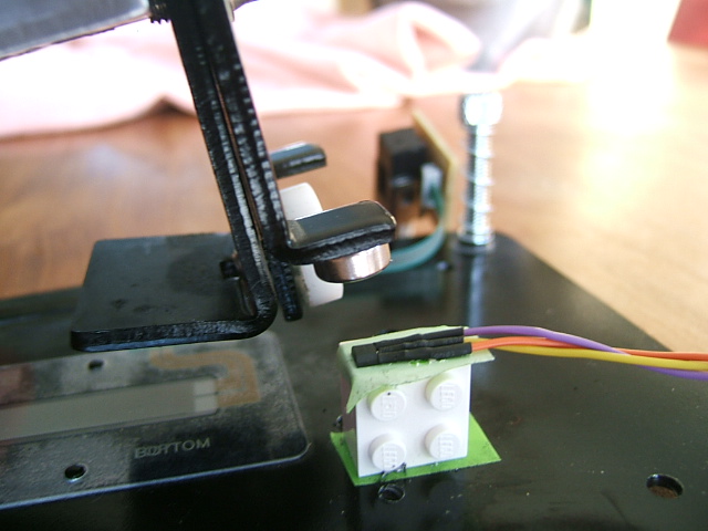
Be careful with the power supply; the Roland power supply states 9V, but it outputs about 12V. Since my Hall Sensor max was 10.5V, a regulator was necessary. 9V seemed a good pick. Using a small Neodymium magnet the sensor had a working range of 4V to 8.2V. I used a plastic Lego brick because it was available and about the right size, and most of all because it was sturdy plastic. After starting of with a metal construction, this was abandoned because I was worried the metal would interfere with the magnetic field and influence the sensor readings.
By making the comparator inputs adjustable with a potmeter, the sensitivity range of the FD-8 half and closed settings can be made very flexible. The circuit is not very complex, so it could very well be made on veroboard or stripboard. I have made a SMT PCB myself, because I prefer working in SMT. Check out the Hall-High-Hat-Hack-Schematic and PCB Layout.
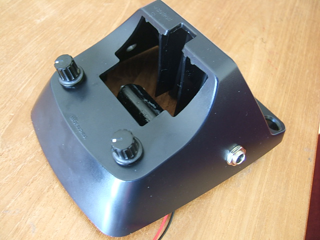
The prototype circuit works very well and makes the HighHat a lot easier to play. Below are some pics. It is not completely finished yet, because the DC connectors haven't arrived yet. The 2.1mm DC Power plugs are intended to make use of the original TD3 power supply; the pedal will feature 2 parallel plugs, one for power input and the TD3 module can be connected to the other power plug.
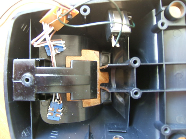
Below are some pics of the not-yet-finished build.
The Magnet sticks to the metal by magnetism, but is also glued with superglue. The Hall Sensor and Lego brick are set using doublesided tape and secured by a tie-wrap (this is not yet in the picture, but the holes can be seen).
The external pots are for adjusting the sensitivity of the closed and half-open state.


